|
Introduction
In the United States, an organization
that supports the common development interests of the cable operators
was created and it is known as CableLabs® (www.cablelabs.org)
. They have defined several standards for the Cable TV industry
that the operators then use to purchase their equipment. One such
standard is for cable modems and it is known as DOCSIS (Data Over
Cable Service Interface Specification).
The major components in a typical Cable
TV system are shown in Figure 1.
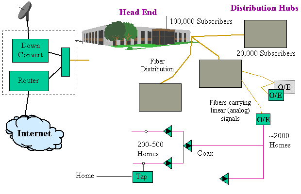
Figure 1. A typical Cable TV system
As shown, the Headend or sometimes called
the Master Head End (MHE), contains the major equipment for the
network. It assembles the program material from the many different
video sources. It also has the main link funneling data from the
cable modem to the Internet.
The Headend serves all customers in a
large geographical area and may typically be 100,000 subscribers.
The headend sends the assembled data and video to branch locations
around the geographic area to a facility known as a Distribution
Hub. A Distribution Hub contains the modulators to put a video
channel on a particular TV channel. (e.g. NBC goes on TV channel
12). It also contains the receivers for data that is sent from
the homes.
The headend uses lasers to feed optical
fibers that spread out across the area. Each fiber will feed approximately
2,000 homes. When the fiber reaches a neighborhood, it is converted
from an optical signal to an electrical signal and split into
four different paths feeding 500 homes. This combination of optical
(fiber) and electrical (coaxial) is called Hybrid Fiber Coax or
HFC for short.
The data signal is carried just like
any other video signal through the system. Unlike the video signal,
the data system also requires a channel that goes back to the
head end since Internet users are interactive. The way the system
carries both the downstream (head end to subscriber) and upstream
(subscriber to head end) signals is by using separate frequencies.
The different versions of DOCSIS
There are currently three generations
of DOCSIS. DOCSIS 1.0 is defined primarily as an Internet access
service for consumers. It allows the single coaxial cable to be
shared by a variety of subscribers in the neighborhood. DOCSIS
1.1 adds the ability to delivery data very accurately allowing
the system to support telephone services. In a system, it is possible
for there to be more than one DOCSIS channel on the system. DOCSIS
1.1 devices can work in DOCSIS 1.0 systems but they loose the
ability to support accurate delivery of data.
DOCSIS 2.0 devices support DOCSIS 1.1
features and add the ability to use higher upstream data rates.
The technical aspects of these three generations will be described
in greater detail in the next few seminars. As a point of reference,
most cable systems deliver data at 27 Mb/s (megabits per second
) on the downstream path. This 27 Mb/s can be done separately
for each fiber link serving 2,000 homes if so desired. Should
more data be required, more than one channel of DOCSIS can be
used.
For upstream data transmissions, the
channel data rates are in the range of 320 Kb/s (Kilobits per
second) to 27 Mb/s). Each user's modem is set by the operator
to some maximum speed thus allowing the operator to charge more
for greater performance.
The suite of DOCSIS specifications
DOCSIS covers several different aspects
of the system to provide the data delivery solution and there
are different specifications for each piece of the system. The
DOCSIS reference model is shown in Figure 2.
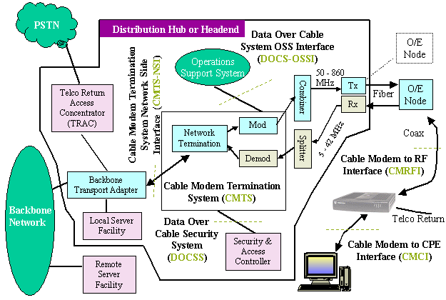
Figure 2. The DOCSIS reference model
DOCSIS covers many aspects of the Cable
network. Included in the architecture are:
-
The link between the PC and the Cable Modem (CM)
-
The link between the CM and the Cable Modem Termination
System (CMTS)
-
Network Management
-
Link Privacy
-
Generic information about the network beyond
the CMTS
In order for a manufacturer to claim
that they meet the DOCSIS specification, CableLabs® puts the
equipment through a compliance test to ensure it meets the requirements.
Most US cable operators will only buy cable modem equipment that
is DOCSIS certified.
The most important specification is the
CMRFI (Cable Modem Radio Frequency Interface) specification that
defines the messages that flow over the coax and into the cable
modem. The description of those messages is in DOCSIS Protocols
seminar. A description of the electrical modulation is contained
in the DOCSIS Physical Layer Technology seminar.
The cable modems you buy in the stores
are compliant to this specification. The cable modem connect with
your computer in one of the several ways specified in the CMCI
(Cable Modem to Computer Interface) specification. These modem
may be internal to the computer, use the Ethernet Interface, Universal
Serial Bus (USB), or the Home Phone Network Architecture (HPNA).
The DOCSIS system also includes security
features (DOCSIS). This security ensure that only valid users
are able to use the system. Security also includes that the data
is encrypted so that a user is assured of privacy of their data.
Management of the system is provided
by the Data Over Cable System Operation Support System Interface
(DOCS-OSSI). This allows the operator to detect problems in the
network, and determine the status, capability and provisioning
of the parameters for the Cable Modem.
Cable Modem Terminating System (CMTS)
The Cable Modem Terminating System (or
CMTS), which is located in the distribution hub, provides the
interface to the HFC network. The CMTS provides the control functions
to arbitrate and schedule transmissions from the many cable modems.
There are many upstream channels for
each downstream channel. In the DOCSIS protocol the CMTS controls
all aspects of managing the bandwidth in both directions on the
link. This control allows for assigning different levels of priority
and bandwidth to each individual cable modem (CM). Because of
the tight control available, upstream and downstream transmission
can be accurately scheduled thus enabling the desired Quality
of Service (QoS) for each type of connection (i.e. voice, video,
and data packets).
The upstream channel is divided into
units of 6.25 ms. These units are called mini-slots, which are
8 bytes long for QPSK or 16 bytes long for 16-QAM. Blocks of mini-slots
are assembled together to transmit variable length packets. Cable
Modems (CM) send requests for the amount of mini-slots that are
needed to send the data packets. The CMTS schedules the proper
number of slots and tells the CM when to transmit the data.
More Information
The DOCSIS specifications are available
at: www.cablemodem.com/specifications.html
.
Additional DOCSIS seminars:
 The DOCSIS Protocol - A description of the messages
between the CMTS and the CM. This includes the mechanism to share
the coax, ranging and registration.
The DOCSIS Protocol - A description of the messages
between the CMTS and the CM. This includes the mechanism to share
the coax, ranging and registration.
The DOCSIS Physical Layer - The downstream/upstream modulation and data rates.
Quality of Service (DOCSIS 1.1) - The changes to DOCSIS
1.0 to implement QoS.
In Summary:
-
DOCSIS was created by CableLabs and they certify
the equipment.
-
DOCSIS is composed of many different specifications
for each major system interface.
-
There are three generations of DOCSIS protocols
and these are backward compatible.
-
The DOCSIS protocol allows complete control of
data being transmitted by the CM thus allowing telephone and
other QoS data streams to be supported.
|