|
Introduction
Network interconnectivity, also known
as internetworking, glues together networks from different vendors,
with different protocol stacks, and utilizing different communications
technologies to form an enterprise wide network. To make these
networks useful, they devices need to have the network identify
them (names), there must be a way of identifying the cause of
troubles in the network (network management), and there must be
a way to forward information betwen networks.
The key devices used in network interconnectivity
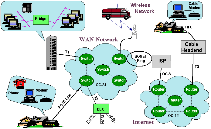
are bridges, routers, and switches. As shown in Figure 1, there
are devices that tie these various networks together. In order
for these devices to perform their functions, there is the concept
of the name of the computers, its address(s) within a network
and the route that will be used to transmit the data between them.

Figure 1. Mixture of Data Networking
Components
Names, Addresses and Routes
In some respects, a computer network
operates with some of the same processes used by people to send
information (letters) to eachother. If you want to contact somebody,
you need their name, an address of where the letter is to go and
then the post office decides on the best route to be used for
the delivery of your information.
Names
Names are usually unique identifier
that can be associated with either a machine function or a user.
Think about names in a phone book. Sometimes the person (name)
may be at the address specified in the book. If we wanted to visit
that person at their home, we would need to travel a route to
get to them. This analogy works well for data networks.
The name and address for a device are unique for each protocol.
Layer 2 and 3 of the OSI protocol stack has its own addressing
mechanism and a computer may be running more than one protocol
at each layer. A good example may be having an IP address (32
bits) running over an Ethernet address (48 bits) over an ATM network
(20 bytes).
The association between names and addresses is not static, that
is it can change. Sometimes a machine may be a server but other
times a new machine can replace the old server. Instead of everyone
changing the address, it is possible to use the services of a
name to address translator. The device that translates names to
address is called a name server. In the Internet, the specific
name is the Domain Name Server (DNS).
Routes
Once a name is translated into a network
address, it becomes possible to find a path to get to that address.
One of the things that separates bridges, switches and routers
is the way they get a packet to its destination.
In a switch, the address must first sent to an intelligent entity
that knows about the entire network. It may find multiple routes
through many switches to get the destination. It would then select
an the best route identify individual switches that must create
the path. Once this path is established, all packets will follow
this same route. At the end this entity must be aware of when
there is no longer a need to maintain this path.
A bridge will learn about the stations that are on its LAN and
forward any packets that have addresses it cannot identify. If
there are multiple bridges on a LAN, each bridge will see if there
is a return message from that destination. If it does not see
a message, there will be no further forwarding. A bridge does
not need to know about the entire network, only about the machines
directly attached to it.
A router examines each packet and performs one of several functions.
It can use a preconfigured table to send it to a destination,
it may learn about a destination similar to a bridge, or it may
ask adjacent routers for help. Routers usually only have a few
ports verses many ports for a switch. It does not need to know
when a connection starts and stops. It only needs to know about
its part of the network verses the entire network.
In summary:
-
A Name
-
An Address
-
is an identifier for
a machine
-
may be a multicast address
which represent multiple destinations (IP, Ethernet, ATM)
-
associated with a name
may change
-
A Route
-
is the path through the
network
-
may have switches which
require a set-up for a session
-
may have Routers/Bridges
which can automatically learn about the network
An example: How names are translated to address for
the Internet
Every computer (host or router) in a
well run part of the Internet has a Name. The name is usually
given to a device by its owner. Internet names are actually hierarchical,
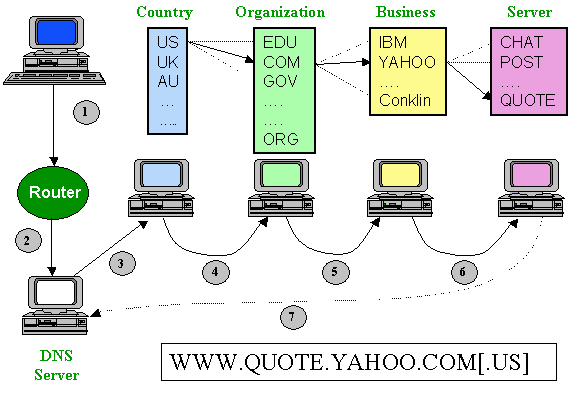
and look rather like postal addresses. For example, the name quote.yahoo.com
directs it to the server for stock price quotes (quote). The company
it is in is called yahoo. The organization is com (for commercial)
and it is in the United States (us). The Internet calls this the
Domain Name System (DNS). Names in this system are "Case
Insensitive", which means that it makes no difference whether
you give them in capitals or not.

Figure 2. Name to Address Translation
In Figure 2, the name from the destination
name is typed into the computer and forwarded (step 1) into the
network. The message is forwarded to the Domain Name Server (step
2) which sends out a message to the country server (step 3), and
forwards it on through the hierarchy of names until the complete
address is found. When it finally gets to a DNS server that knows
the destination's address, the last DNS server returns the address
to the original DNS server (step 7).
One of the benefits of using this hierarchical system is that
not every DNS computer needs to know the name of every computer
in the world (a rather large database!). Thus a company would
only need to alter the list for its servers and not worry about
all the other servers in the world. The primary disadvantage is
that it takes several steps to resolve the name.
Everything in any part of the Internet that wants to be reached
must have an address. The address tells the computers in the Internet
(hosts and routers) where something is topologically. Thus the
address is also hierarchical. The Conklin Corporation server address
is 38.229.67.213. It was assigned by the IANA (Internet Assigned
Numbers Authority) for a network number.
For large companies with Class B addresses, it might be given
the number 127.99.x.y. The company can fill in the x and y as
they like. Too number the computers in a network, divide the computers
into groups on different LAN segments, and number the segments
1-256 (x), and then the hosts 1-256 (y) on each segment. When
an organization asks for a number for its net, it will be asked
how many computers it has, and assigned a network number big enough
to accommodate that number of computers.
Everything in the Internet must be reachable. The route to a host
will traverse one or more networks. The easiest way to picture
a route is by thinking of how a letter to a friend in a foreign
country gets there.
You post the letter in a postbox. It is picked up by a postman
(LAN), and taken to a sorting office (router). There, the sorter
looks at the address, and sees that the letter is for another
country, and sends it to the sorting office for international
mail. This then carries out a similar procedure. And so on, until
the letter gets to its destination. If the letter was for the
same 'network' then it would get immediately locally delivered.
Notice the fact that all the routers (sorting offices) don't have
to know all the details about everywhere, just about the next
hop to go to. Notice the fact that the routers (sorting offices)
have to consult tables of where to go next (e.g. international
sorting office). Routers chatter to each other all the time figuring
out the best (or even just usable) routes to places.
One way to picture this is to imagine a road system with a person
standing at every intersection who is working for the Road Observance
Brigade. This person (Rob) reads the road names of the roads meeting
at the intersection, and writes them down on a card, with the
number 0 after each name. Every few minutes, Rob holds up the
card to any neighbor standing down the road at the next intersection.
If they are doing the same, Rob writes down their list of names,
but adds 1 to the numbers read off the other card. After a while,
Rob is now telling people about the neighbors roads several roads
away! Of course, Rob might get two ways to get somewhere! Then,
he crosses out the one with the larger number.
The Basics of Bridging, Routing and Switching
Bridges, switches and routers are devices
that connect networks together. All three of these technologies
are useful and apply to different portions of the network.
Bridges and switches are a data communications
devices that operate principally at Layer 2 of the OSI reference
model. A principle difference between these two technologies is
that switches must have the route of the packet determined before
the first packet can traverse the network. Bridges can make packet
forwarding decisions dynamically.

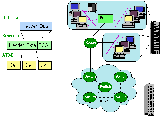
Figure 3. A Network Utilizing Bridges, Router and Switches
In Figure 3, all three internetworking
devices are shown working simultaneously. A bridge connects two
similar or dissimilar LANs to form a larger network at the data-link
layer (layer 2). Bridges are simple devices and do not deal with
any higher-level issues such as network routing and session control.
Bridges require that the networks have consistent addressing schemes
and packet sizes. Their primary usage is:
-
Interconnections of LANs
with different layer 1 technologies. Bridges are used frequently
to connect Ethernet LANs. For example, many bridges connect
thin wire Ethernet to thickwire Ethernet. A bridge between
two LANs will basically read a message from the first LAN
and pass only the messages destined for the second LAN.
-
Bridges can be used to divide
a large network into smaller subnets to control traffic. For
example, consider an Ethernet LAN with 100 stations. Since
all 100 stations chattering simultaneously can cause collisions,
a bridge can be used to subdivide the network into two 50
stations LANs.
The biggest advantage of a switch is
that it is aware of the presense of a session between two computers.
This allows the switch to provide different leverls of service
to each type of connection based on the needs of each of the sessions.
For example, a voice conncection requires a constant data rate
and very low delays between the computers. A computer browsing
the Internet can tolerate variations in the delay between the
computers.
A router operates at layer 3. It finds
a path for a message and then sends the message on the selected
path. A router may appear to be the same as a bridge, but the
main distinguishing feature of a router is that it knows alternate
routes for a message and uses the alternate route to send a message
if the primary route is not available. Consequently, a router
must know the network topology (a layer 3 issue). Owing to their
router algorithms, routers are more complex and expensive than
bridges.
In Summary:
-
Switches
-
Bridges
-
forwards packets based
on the layer 2 address. (Medium cost)
-
learn which devices are
on both sides of the its interfaces (usually 2 interfaces)
-
filter packets (hop count)
-
Routers
-
Based on layer 3 information
(protocol specific)
-
Finds path through network
/ shares information
-
Filters out broadcast
messages for layer 2
-
Highest cost (factor
of 3)
For more
details on how these devices work, click on the following:
Network Management
In the late 1970's, computer networks
had grown from a simple layout of small, separate networks that
were not connected to each other to larger networks that were
interconnected. These larger networks were called internets and
their size grew at an exponential rate. The larger these networks
became the more difficult they became to manage (i.e.. monitor
and maintain), and it soon became evident that a network management
protocol need be developed.
The first protocol used was the Simple Network Management Protocol
(SNMP). It was commonly considered to be a quickly designed "band-aid"
solution to internetwork management difficulties while other,
larger and better protocols were being designed. The five main
functions are fault management, configuration management, security
management, performance management, and accounting management.
To aid in the task of managing the network,
network protocols are used so that the process is automated (i.e.
run by computers) as much as possible.
Simple Network Management Protocol (SNMP) and Common Management
Information Protocol (CMIP) are two of the network management
protocols. Generally, SNMP works under the TCP/IP (Transport Control
Protocol/ Internet Protocol) communication stack and CMIP works
under the OSI (Open Systems Interconnection) communication stack.
SNMP is designed to facilitate the exchange of management information
between network devices. By using SNMP to access management information
data (such as packets per second and network error rates), network
administrators can more easily manage network performance and
find and solve network problems. SNMP is a relatively simple protocol,
yet its feature set is sufficiently powerful to handle the difficult
problems presented by management of heterogeneous networks.
CMIP is used with the Common Management Information Services (CMIS).
CMIS defines a system of network management information services.
CMIP was proposed as a replacement for the less sophisticated
Simple Network Management Protocol (SNMP) but has not been widely
adopted. CMIP provides improved security and better reporting
of unusual network conditions.
The information the SNMP and CMIP can attain from a network is
defined as a MIB (management information base). The MIB is structured
like a tree. At the top of the tree is the most general information
available about a network. Each branch of the tree then gets more
detailed into a specific network area, with the leaves of the
tree as specific as the MIB can get. For instance, devices may
be a parent in the tree, its children being serial devices and
parallel devices. The value of these may be 6 , 2, 4 accordingly;
with the numbers corresponding to the number of devices attached
(4 parallel + 2 serial = 6 total devices). Each node in the MIB
tree is a variable (hence in the above example, devices, serial
devices, and parallel devices are all variables, their values
being 6, 2, 4 accordingly). The top of a LAN MIB tree is usually
referred to as "Internet".
The CMIP protocol was supposed to be the protocol that replaced
SNMP in the late 1980's. Funded by governments and large corporations,
many thought that it would become a reality because of its almost
unlimited development budget. Unfortunately, problems with its
implementation have delayed its widespread availability and it
is now only available in limited form from its developers themselves.
CMIP was designed to build on SNMP by making up for SNMP's shortcomings
and becoming a bigger, more detailed network manager. Its basic
design is similar to SNMP, whereby PDU's are employed as variables
to monitor a network. CMIP however contains 11 types of PDU's
(compared to SNMP's five).
In CMIP, the
variables are seen as very complex and sophisticated data structures,
with many attributes.
These include:
-
variable attributes: which
represent the variables characteristics (its data type, whether
it is writable).
-
variable behaviors: what
actions of that variable can be triggered.
-
Notifications: the variable
generates an event report whenever a specified event occurs
(e.g.. a terminal shutdown would cause a variable notification
event.
As a comparison, SNMP only employs variable
properties one and three from above.
Additional information is available for:
 Bridges - A description of the four main types of bridges.
 Routers - A description of the various types of routers
and how they work
 IP addressing - A description of the four types of
IP addresses, public/private addresses, and
static/dynamic addresses.
 Network Managment - How these systems monitor complex
networks.
|

