|
Introduction
Bridges are devices that pass packets
between two LANs. The biggest benefit of a bridge is to create
smaller networks which can greatly increase the overall performance.
In a LAN sharing a common wire, when one computer is talking all
others must be listening. If a network of 100 computers is broken
into two networks of 50 computers the overall bandwidth is doubled.
The bridge connecting these two LAN segments allows a computer
on one LAN to talk to a computer on the other LAN.
Bridges operate on the OSI layer 2 (i.e..
Ethernet) and they are often confused with routers that operate
on the OSI layer 3. There are several types of bridges commonly
used and each type has advantages and disadvantages. The basic
types of bridging algorithms are transparent, spanning tree, source-routing,
and source-routing transparent.
The Institute of Electrical and Electronic
Engineers (IEEE) has divided the OSI link layer into two separate
sublayers: the Media Access Control (MAC) sublayer and the Logical
Link Control (LLC) sublayer. The MAC sublayer permits and orchestrates
media access (for example, contention, token passing, or others),
while the LLC sublayer is concerned with framing, flow control,
error control, and MAC-sublayer addressing.
Some bridges are MAC-layer bridges. These devices bridge between
homogeneous networks (for example, IEEE 802.3 and IEEE 802.3).
Other bridges can translate between different link-layer protocols
(for example, IEEE 802.3 and IEEE 802.5). A bridge's translation
between networks of different types is never perfect because it
is likely that one network will support certain frame fields and
protocol functions not supported by the other network.
Transparent Bridging
The simplest kind of bridge is called
a transparent bridge. Transparent bridges are so named because
their presence and operation are transparent to network hosts.
When transparent bridges are powered on, they learn the network's
topology by analyzing the source address of incoming frames from
all attached networks. If, for example, a bridge sees a frame
arrive on line 1 from Host A, the bridge concludes that Host A
can be reached through the network connected to line 1. Through
this process, transparent bridges build a table which is the basis
for traffic forwarding.
Transparent bridges successfully isolate intrasegment traffic,
thereby reducing the traffic seen on each individual segment.
This usually improves network response times as seen by the user.
The extent to which traffic is reduced and response times are
improved depends on the volume of intersegment traffic relative
to the total traffic as well as the volume of broadcast and multicast
traffic.
Transparent Bridges operate according
to the following rules:
1. Examine all packets on all active network ports for their source
address.
2. Maintain a table that tracks which port a source address has
appeared on.
3. Look up the destination addresses in this table for all packets,
and if a packet's matching port is
different than the port it was received
on, forward the packet to the matching port.
4. If no match is found, or if the destination address is the
broadcast address, forward the packet out all
active ports.
This scheme is acceptable on very simple network topologies. It
will not work correctly if there are multiple paths to the same
destination. In this case, packets will be forwarded in a "bridging
loop" which will quickly use up the available network bandwidth
on the segments in question.
Bridging Loops
Without a bridge-to-bridge protocol,
the transparent bridge algorithm fails when there are multiple
paths of bridges and local-area networks (LANs) between any two
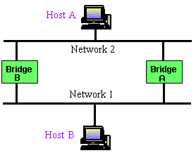
LANs in the internetwork. Figure 1 illustrates such a bridging
loop.

Figure 1. Inaccurate Forwarding and Learning in Transparent
Bridging Environments
Suppose Host A sends a frame to Host B. Both bridges receive the
frame and correctly conclude that Host A is on Network 2. Unfortunately,
after Host B receives two copies of Host A's frame, both bridges
will again receive the frame on their network 1 interfaces because
all hosts receive all messages on broadcast LANs. In some cases,
the bridges will then change their internal tables to indicate
that Host A is on network 1. If so, when Host B replies to Host
A's frame, both bridges will receive and subsequently drop the
replies because their tables will indicate that the destination
(Host A) is on the same network segment as the frame's source.
In addition to basic connectivity problems such as the one just
described, the proliferation of broadcast messages in networks
with loops represents a potentially serious network problem. Referring
again to Figure 1, assume that Host A's initial frame is a broadcast.
Both bridges will forward the frames endlessly, using all available
network bandwidth and blocking the transmission of other packets
on both segments.
A topology with loops such as that shown in Figure 1 can be useful
as well as potentially harmful. A loop implies the existence of
multiple paths through the internetwork. A network with multiple
paths from source to destination can increase overall network
fault tolerance through improved topological flexibility.
Spanning-Tree Bridging
To avoid bridging loops, an algorithm
was developed which lets bridges shut off ports which provide
duplicate paths to the same destination. The algorithm relies
on the use of Bridge Protocol Data Units (BPDU packets), which
provide information to all bridges about the "distance"
in hops to each bridge port from a "root bridge." The
root bridge is selected using settings entered into each bridge
(with the Ethernet address acting as a tie-breaker).
Using BPDU information, a bridge can determine whether one of
its ports provides an optimal path to the root bridge. If it does
not, the port is shut down. If the path distance is optimal but
is the same as another bridge's path, a simple protocol allows
one of the ports to be shut down. In all other respects, spanning
tree bridges operate in the same fashion as simple learning bridges.
Spanning-Tree Algorithm (STA)
The spanning-tree algorithm (STA) was
developed to preserve the benefits of loops while eliminating
their problems. The STA designates a loop-free subset of the network's
topology by placing those bridge ports that, if active, would
create loops into a standby (blocking) condition. Blocking bridge
ports can be activated in the event of primary link failure, providing
a new path through the internetwork.
The STA uses a conclusion from graph
theory as a basis for constructing a loop-free subset of the network's
topology. Graph theory states the following:
"For any connected graph consisting
of nodes and edges connecting pairs of nodes, there is a spanning
tree of edges that maintains the connectivity of the graph but
contains no loops."
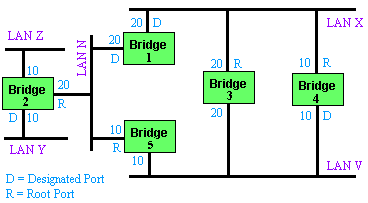
Figure 2 illustrates how the STA eliminates
loops. The STA calls for each bridge to be assigned a unique identifier.
Typically, this identifier is one of the bridge's Media Access
Control (MAC) addresses plus a priority. Each port in every bridge
is also assigned a unique (within that bridge) identifier (typically,
its own MAC address). Finally, each bridge port is associated
with a path cost. The path cost represents the cost of transmitting
a frame onto a LAN through that port. In Figure 2, path costs
are noted on the lines emanating from each bridge. Path costs
are usually defaulted, but can be assigned manually by network
administrators.

Figure 2. Transparent Bridge Network before Running STA
The first activity in spanning-tree
computation is the selection of the root bridge, which is the
bridge with the lowest value bridge identifier. In Figure 2, the
root bridge is Bridge 1. Next, the root port on all other bridges
is determined. A bridge's root port is the port through which
the root bridge can be reached with the least aggregate path cost.
This value (the least aggregate path cost to the root) is called
the root path cost.
Finally, designated bridges and their designated ports are determined.
A designated bridge is the bridge on each LAN that provides the
minimum root path cost. A LAN's designated bridge is the only
bridge allowed to forward frames to and from the LAN for which
it is the designated bridge. A LAN's designated port is the port
that connects it to the designated bridge.
In some cases, two or more bridges can have the same root path
cost. For example, in Figure 2, Bridges 4 and 5 can both reach
Bridge 1 (the root bridge) with a path cost of 10. In this case,
the bridge identifiers are used again, this time to determine
the designated bridges. Bridge 4's LAN V port is selected over
Bridge 5's LAN V port.
Using this process, all but one of the bridges directly connected
to each LAN are eliminated, thereby removing all two-LAN loops.
The STA also eliminates loops involving more than two LANs, while
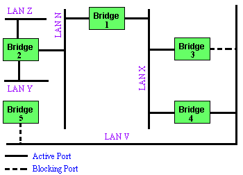
still preserving connectivity. Figure 28 shows the results of
applying the STA to the network shown in Figure 2. Figure 3 shows
the tree topology more clearly. Comparing this figure to the pre-spanning-tree
figure shows that the STA has placed both Bridge 3's and Bridge
5's ports to LAN V in standby mode.

Figure 3. Transparent Bridge Network After Running STA
The spanning-tree calculation occurs
when the bridge is powered up and whenever a topology change is
detected. The calculation requires communication between the spanning-tree
bridges, which is accomplished through configuration messages
(sometimes called bridge protocol data units, or BPDUs). Configuration
messages contain information identifying the bridge that is presumed
to be the root (root identifier) and the distance from the sending
bridge to the root bridge (root path cost). Configuration messages
also contain the bridge and port identifier of the sending bridge
and the age of information contained in the configuration message.
Bridges exchange configuration messages at regular intervals (typically
one to four seconds). If a bridge fails (causing a topology change),
neighboring bridges will soon detect the lack of configuration
messages and initiate a spanning-tree recalculation.
All transparent bridge topology decisions are made locally. Configuration
messages are exchanged between neighboring bridges. There is no
central authority on network topology or administration.
Source-Route Bridging
The source-route bridging (SRB) algorithm
was developed by IBM and proposed to the IEEE 802.5 committee
as the means to bridge between all local-area networks (LANs).
Subsequently, IBM has offered a new bridging standard to the IEEE
802 committee: the source-route transparent (SRT) bridging solution.
SRT bridging eliminates pure SRBs entirely, proposing that the
two types of LAN bridges be transparent bridges and SRT bridges.
Although SRT bridging has achieved support, SRBs are still widely
deployed.
SRB Algorithm
SRBs are so named because they assume
that the complete source-to-destination route is placed in all
inter-LAN frames sent by the source. SRBs store and forward the
frames as indicated by the route appearing in the appropriate
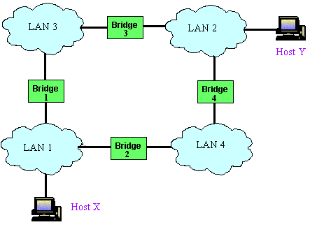
frame field. Figure 4 illustrates a sample SRB network.

Figure 4. SRB Network Diagram
Referring to Figure 4, assume that Host
X wishes to send a frame to Host Y. Initially, Host X does not
know whether Host Y resides on the same or a different LAN. To
determine this, Host X sends out a test frame. If that frame returns
to Host X without a positive indication that Host Y has seen it,
Host X must assume that Host Y is on a remote segment.
To determine the exact remote location of Host Y, Host X sends
an explorer frame. Each bridge receiving the explorer frame (Bridges
1 and 2 in this example) copies the frame onto all outbound ports.
Route information is added to the explorer frames as they travel
through the internetwork. When Host X's explorer frames reach
Host Y, Host Y replies to each individually using the accumulated
route information. Upon receipt of all response frames, Host X
chooses a path based on some predetermined criteria.
In the example
in Figure 4, this process will yield two routes:
Host X must
select one of these two routes. The IEEE 802.5 specification does
not mandate the criteria Host X should use in choosing a route,
but it does make several suggestions, including the following:
-
First frame received
-
Response with the minimum number of hops
-
Response with the largest allowed frame size
-
Various combinations of the above criteria
In most cases, the path contained in
the first frame received will be used.
After a route is selected, it is inserted into frames destined
for Host Y in the form of a routing information field (RIF). A
RIF is included only in those frames destined for other LANs.
The presence of routing information within the frame is indicated
by the setting of the most significant bit within the source address
field, called the routing information indicator (RII) bit.
Source-Route Transparent Bridging
Source-Route Transparent (ART) bridges
combine implementations of the transparent bridging and the Source
Routing bridging algorithms. ART bridges use the Routing Information
Indicator (RII) bit to distinguish between frames employing FRB
and frames employing transparent bridging. If the RII bit is 1,
a Routing Information Frame (RIF) is present in the frame, and
the bridge uses the SRB algorithm. If the RII bit is 0, an RIF
is not present, and the bridge uses transparent bridging.
Like translational bridges, SRT bridges are not perfect solutions
to the problems of mixed-media bridging. SRT bridges must still
deal with the Ethernet/Token Ring incompatibilities described
earlier. SRT bridging is likely to require hardware upgrades to
SRBs to allow them to handle the increased burden of analyzing
every packet. Software upgrades to SRBs may also be required.
Further, in environments of mixed SRT bridges, transparent bridges,
and SRBs, source routes chosen must traverse whatever SRT bridges
and SRBs are available. The resulting paths can potentially be
substantially inferior to spanning-tree paths created by transparent
bridges. Finally, mixed SRB/SRT bridging networks lose the benefits
of SRT bridging, so users will feel compelled to execute a complete
cutover to SRT bridging at considerable expense. Still, SRT bridging
permits the coexistence of two incompatible environments and allows
communication between SRB and transparent bridging end nodes.
Summary
In summary,
the four major bridging algorithms in use today are:
-
Transparent Bridging (TB)
-
Spanning Tree Bridging
-
Source-Routed Bridge (SRB)
-
Source-Routed Transparent Bridge (SRTB)
|

