|
Introduction
Asynchronous Transfer Mode or ATM, is
a communications technology primarily used in the backbone of
high speed networks. It supports real-time voice and video as
well as data establishing connections between the two endpoints.
These connections may establish guarantees a quality of service
(QoS) for that data transmission. However, unlike telephone switches
that dedicate circuits end to end, unused bandwidth in ATM's logical
circuits can be utilized whenever available. For example, idle
bandwidth in a videoconference circuit can be used to transfer
data.
ATM works by transmitting all traffic as fixed-length units called
cells which are 53-bytes long. This fixed unit allows very fast
switches to be built, because the processing associated with variable-length
packets is eliminated (finding the end of the frame). The small
ATM cells also ensure that voice and video can be intermixed because
there are no long delays encountered because of large packets.
ATM transfers information in fixed-size. Each cell consists of
53 octets, or bytes. The first 5 bytes contain cell-header information,
and the remaining 48 contain the "payload" (user information).
Figure 1 illustrates the basic format of an ATM cell.
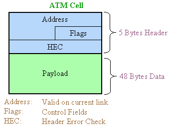
Figure 1. The ATM cell
The ATM standard actually consists of
many different aspects required to effectively transmit information
and manage the network. The various aspects of the standard include
establishing connections, Quality of Service (QoS), User-to-Network
Interface (UNI), Network-to-Network Interface (NNI), Management,
and Interface Diagnostics.
ATM Reference Model
Computer users
want to transmit messages and in order to do that, they need multiple
layers of communications protocols. For example, users wanting
to browse the web use TC/IP. These packets are carried over Ethernet
and somewhere in the network, these packets may get converted
into ATM cells. The ATM reference model, shown in Figure 2, is
composed of the following OSI layers:
-
Physical layer --- Analogous to the physical
layer of the OSI reference model, the ATM physical layer manages
the medium-dependent transmission.
-
ATM layer --- Combined with the ATM adaptation
layer, the ATM layer is roughly analogous to the data-link
layer of the OSI reference model. The ATM layer is responsible
for establishing connections and passing cells through the
ATM network. To do this, it uses information in the header
of each ATM cell.
-
ATM Adaptation Layer (AAL) --- Combined with
the ATM layer, the AAL is roughly analogous to the data-link
layer of the OSI model. The AAL is responsible for isolating
higher-layer protocols from the details of the ATM processes.
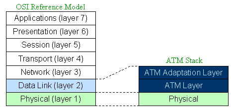
Figure 2. Comparing the OSI reference model with
the ATM reference model
For a more complete explanation of the
OSI layers, please see our seminar Communications
Layers.
The ATM physical layer performs the following
functions: Bits are converted into cells; the transmission and
receipt of bits on the physical medium are controlled; ATM cell
boundaries are tracked; and cells are packaged into the appropriate
type of frame for the physical medium.
The ATM Adaptation Layer (AAL) performs
the function of taking packets from the upper layer protocols
such as Ethernet or TCP/IP and segmenting them. There are actually
several different ways larger packets may be segmented into the
smaller ATM cells. The selection of the proper AAL is dependent
on the physical links being used and the type of data being transmitted.
For more information on the process used
to segment larger packets into cells and then reassemble the cells
back into packets, please see the seminar ATM Adaptation Layers.
ATM Networks
An ATM network consists of a set of ATM
switches interconnected by point-to-point ATM links or interfaces.
ATM switches support two primary types of interfaces: user-network
interface (UNI) and network-node interface (NNI). The UNI connects
ATM end-systems (such as hosts and routers) to an ATM switch.
The NNI connects two ATM switches.
Depending on whether the switch is owned
and located at the customer's premises or publicly owned and operated
by the telephone company, UNI and NNI can be further subdivided
into public and private UNIs and NNIs. A private UNI connects
an ATM endpoint and a private ATM switch. Its public counterpart
connects an ATM endpoint or private switch to a public switch.
A private NNI connects two ATM switches within the same private
organization. A public one connects two ATM switches within the
same public organization.
An additional specification, the Broadband
Interexchange Carrier Interconnect (B-ICI), connects two public
switches from different service providers. Figure 3 illustrates
the ATM interface specifications for private and public networks.
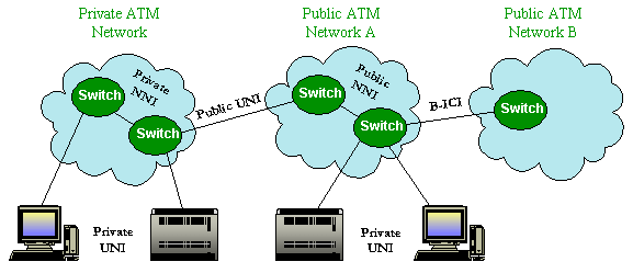
Figure 3. ATM interface specifications differ for
private and public networks
ATM Cell-Header Format
An ATM cell header can be one of two
formats: UNI, or the NNI. The UNI header is used for communication
between ATM endpoints and ATM switches in private ATM networks.
The NNI header is used for communication between ATM switches.
Figure 3 depicts the basic ATM cell format, the ATM UNI cell-header
format, and the ATM NNI cell-header format.
Unlike the UNI, the NNI header does not
include the Generic Flow Control (GFC) field. Additionally, the
NNI header has a Virtual Path Identifier (VPI) field that occupies
the first 12 bits, allowing for larger trunks between public ATM
switches.
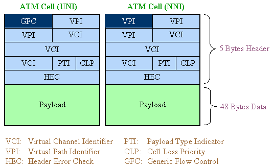
Figure 4. Two forms of ATM cells, UNI and NNI Formats
ATM Cell-Header Fields
In: addition
to GFC and VPI header fields, several others are used in ATM cell-header
fields. The following descriptions summarize the ATM cell-header
fields illustrated in Figure 4:
-
Generic Flow Control (GFC) --- Provides local
functions, such as identifying multiple stations that share
a single ATM interface. This field is typically not used and
is set to its default value.
-
Virtual Path Identifier (VPI) --- In conjunction
with the VCI, identifies the next destination of a cell as
it passes through a series of ATM switches on the way to its
destination.
-
Virtual Channel Identifier (VCI) --- In conjunction
with the VPI, identifies the next destination of a cell as
it passes through a series of ATM switches on the way to its
destination.
-
Payload Type (PT) --- Indicates in the first
bit whether the cell contains user data or control data. If
the cell contains user data, the second bit indicates congestion,
and the third bit indicates whether the cell is the last in
a series of cells that represent a single AAL5 frame.
-
Congestion Loss Priority (CLP) --- Indicates
whether the cell should be discarded if it encounters extreme
congestion as it moves through the network. If the CLP bit
equals 1, the cell should be discarded in preference to cells
with the CLP bit equal to zero.
-
Header Error Control (HEC) --- Calculates checksum
only on the header itself.
More Information
The ATMForum has specifications available
at: www.atmforum.com.
Additional ATM seminars:
 ATM Connection Management - A description of how connections
are established, Quality of Service (QoS), and Virtual Connections
(PVCs and SVCs).
ATM Connection Management - A description of how connections
are established, Quality of Service (QoS), and Virtual Connections
(PVCs and SVCs).
The ATM Adaptation Layers (AAL) - Large data packets
are required to be segmented into the smaller ATM cells and later
the ATM cells are reassembled back into packets. There are several
different AALs that can be used based on the type of data being
transported.
In Summary:
-
ATM is a layer 2 protocol that and able to transport
an upper layer protocol (Layer 3-4).
-
ATM is connection oriented and can support Quality
of Service (QoS).
-
There are several deferent types of ATM cells
(NNI, UNI).
|